English
Gate Design Optimization for High Precision Injection Molding
Writer:admin Time:2024-06-05 00:00 Browse:views
Gate Design Optimization for High Precision Injection Molding
In high precision plastic injection molding, gate design directly influences dimensional accuracy, surface quality, cycle stability, weld line formation, internal stress distribution, and long-term product reliability. For industries such as automotive electronics, medical devices, optical components, connectors, and precision industrial equipment, gate optimization is not simply a mold design detail — it is a critical engineering factor that determines production yield and process capability.
As tolerance requirements tighten toward ±0.02 mm or even ±0.005 mm, traditional gate selection based only on mold filling convenience becomes insufficient. Modern precision molding requires integrated gate engineering involving rheology analysis, thermal management, pressure balance, molecular orientation control, and automated process consistency.
This article explores advanced gate design optimization strategies for high precision injection molding, including gate type selection, dimensional calculation, pressure management, shear control, simulation validation, and real-world industrial case studies.
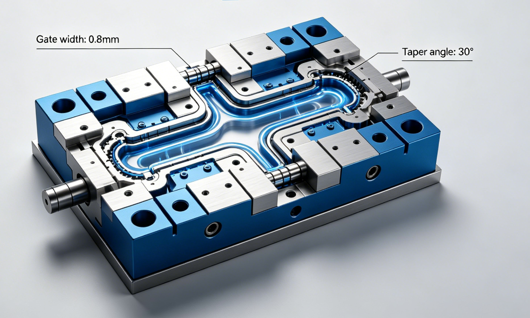
Why Gate Design Matters in Precision Injection Molding
The gate is the transition area between the runner system and the molded part cavity. Although physically small, it governs several critical molding behaviors:
Melt flow direction
Pressure transmission efficiency
Shear rate
Molecular orientation
Packing effectiveness
Cooling balance
Gate freeze timing
Residual stress concentration
Improper gate design often causes:
Warpage
Sink marks
Short shots
Flash
Dimensional instability
Uneven shrinkage
Surface blemishes
Fiber orientation defects
Optical distortion
For precision products, even minor gate-related defects can result in assembly failures or unacceptable CpK performance.
Key Objectives of Precision Gate Design
The engineering goals of gate optimization differ from conventional molding.
Core Objectives
| Objective | Engineering Impact |
|---|---|
| Uniform cavity filling | Reduces internal stress |
| Balanced pressure transmission | Improves dimensional consistency |
| Controlled shear rate | Prevents material degradation |
| Proper gate freeze timing | Ensures packing efficiency |
| Minimal weld lines | Enhances structural integrity |
| Reduced orientation variation | Improves stability |
| Easy degating | Supports automation |
| Short cycle time | Improves production efficiency |
Common Gate Types for Precision Injection Molding
Different gate styles produce different melt flow behaviors and stress distributions.
Comparison of Precision Gate Types
| Gate Type | Advantages | Limitations | Typical Applications |
|---|---|---|---|
| Pin Gate | Automatic degating, balanced filling | High shear stress | Multi-cavity precision parts |
| Submarine Gate | Hidden gate mark | Difficult maintenance | Consumer electronics |
| Fan Gate | Uniform flow distribution | Larger vestige | Thin-wall parts |
| Edge Gate | Simple machining | Uneven pressure distribution | Medium precision parts |
| Valve Gate | Excellent pressure control | High mold cost | Automotive and medical |
| Diaphragm Gate | Uniform radial filling | Complex trimming | Cylindrical components |
| Film Gate | Reduced orientation stress | Larger gate trimming area | Optical parts |
For ultra-precision molding, valve gates and optimized pin gates dominate due to superior process control.
Gate Location Optimization
Gate position is often more important than gate type itself.
Incorrect gate placement can create:
Air traps
Hesitation flow
Differential shrinkage
Excessive orientation
Localized overpacking
Gate Position Engineering Principles
1. Shortest Flow Length
The gate should minimize total flow distance to reduce pressure loss.
2. Uniform Wall Thickness Transition
Avoid gating into abrupt thickness changes because this causes:
Jetting
Sink marks
Flow hesitation
3. Critical Dimension Protection
Never place the gate directly near high-tolerance functional surfaces unless necessary.
4. Symmetrical Filling
Symmetrical filling reduces:
Warpage
Residual stress
Differential shrinkage
Gate Size Optimization
Gate dimensions strongly influence cavity pressure and freeze behavior.
Engineering Relationships
Smaller gates:
Increase shear rate
Improve automatic degating
Reduce vestige
Increase pressure drop
Larger gates:
Improve packing efficiency
Reduce shear heating
Increase cycle time
Risk overpacking
The optimal design balances all variables.
Recommended Gate Dimension Guidelines
| Material Type | Typical Gate Thickness (% of wall thickness) | Shear Sensitivity |
|---|---|---|
| PC | 50–80% | Medium |
| ABS | 40–70% | Low |
| POM | 30–60% | High |
| PA66 GF30 | 60–90% | Medium |
| LCP | 20–40% | Very High |
| PMMA | 50–80% | High |
| PEEK | 60–100% | High |
Engineering-grade resins require customized gate tuning based on viscosity curves.
Shear Rate Control in Precision Molding
Excessive shear at the gate can degrade polymers and destabilize dimensions.
High Shear Problems
| Defect | Root Cause |
|---|---|
| Burn marks | Thermal degradation |
| Silver streaks | Moisture vaporization |
| Brittleness | Molecular chain damage |
| Optical haze | Orientation distortion |
| Gate blush | Surface stress |
For sensitive materials such as LCP, PEEK, and transparent PC, shear optimization is essential.
Gate Freeze Time Optimization
Gate freeze time determines how long packing pressure can compensate for shrinkage.
If the gate freezes too early:
Sink marks increase
Internal voids form
Dimensional instability rises
If too late:
Cycle time increases
Overpacking may occur
Stress accumulation worsens
Precision molders often use cavity pressure sensors to determine actual gate freeze timing instead of relying solely on theoretical calculations.
Hot Runner Gate Optimization
Hot runner systems are widely used in high precision molding because they reduce pressure loss and improve process consistency.
Advantages of Hot Runner Gates
| Benefit | Impact |
|---|---|
| Stable melt temperature | Better repeatability |
| Lower material waste | Reduced cost |
| Faster cycle time | Higher productivity |
| Improved balance | Better dimensional control |
| Lower injection pressure | Reduced machine stress |
Valve gate systems further enhance process capability by enabling sequential filling and precise packing control.
Valve Gate Technology in Precision Applications
Valve gating is increasingly preferred for:
Automotive sensor housings
Medical cartridges
Optical lenses
Thin-wall electronics
Valve Gate Advantages
Eliminates gate drool
Reduces stringing
Improves surface appearance
Allows sequential gating
Enhances cavity pressure consistency
Servo-controlled valve gates provide even higher precision compared to pneumatic systems.
Mold Flow Simulation for Gate Optimization
Modern gate engineering heavily depends on CAE simulation.
Typical software includes:
Moldflow
Moldex3D
Sigmasoft
Cadmould
Simulation evaluates:
Flow front progression
Pressure distribution
Weld line location
Air traps
Fiber orientation
Cooling imbalance
Warpage trends
Simulation dramatically reduces trial-and-error tooling adjustments.
Scientific Molding and Gate Validation
Precision gate optimization must be validated using scientific molding methods.
Critical Validation Parameters
| Parameter | Purpose |
|---|---|
| Cavity pressure curve | Packing verification |
| Gate seal study | Freeze timing analysis |
| DOE analysis | Process window optimization |
| Weight consistency | Filling stability |
| CpK measurement | Statistical capability |
| Short shot study | Flow balance evaluation |
Without process validation, even well-designed gates may fail in mass production.
Fiber-Reinforced Material Gate Challenges
Glass-filled engineering plastics create additional gate complexity.
Common Problems
Fiber breakage
Uneven orientation
Warpage anisotropy
Surface floating fibers
Gate orientation strongly influences fiber alignment direction.
For structural components, gate design must align fiber orientation with mechanical load paths.
Thin-Wall Precision Molding Gate Strategies
Thin-wall products require specialized gate engineering because melt freezes rapidly.
Typical examples include:
Connector housings
Medical microfluidic parts
Battery components
Electronic frames
Thin-Wall Gate Recommendations
| Wall Thickness | Recommended Gate Type | Key Consideration |
|---|---|
| >1.5 mm | Edge/Fan Gate | Balanced filling |
| 0.8–1.5 mm | Pin/Valve Gate | Pressure efficiency |
| 0.3–0.8 mm | Film Gate | Shear reduction |
| <0.3 mm | Specialized micro gate | Ultra-high speed filling |
Ultra-thin molding often requires injection speeds exceeding 300 mm/s.
Gate Vestige Reduction Techniques
Precision cosmetic products require minimal visible gate marks.
Methods include:
Tunnel gate polishing
Sequential valve gating
Reverse flow gating
Film gate distribution
Laser degating
Micro pin gate optimization
In consumer electronics, gate vestige targets may be below 0.05 mm.
Multi-Cavity Precision Mold Balancing
In multi-cavity molds, gate imbalance creates cavity-to-cavity variation.
Balance Optimization Techniques
| Method | Purpose |
|---|---|
| Naturally balanced runner | Equal flow distance |
| Artificial balancing | Pressure compensation |
| Sequential valve gating | Controlled filling |
| Cavity pressure sensors | Real-time monitoring |
| Mold temperature zoning | Thermal balance |
High cavitation medical molds may require cavity variation below ±0.3%.
Cooling and Gate Interaction
Gate regions often become thermal hotspots.
Poor cooling near the gate causes:
Differential shrinkage
Local warpage
Extended cycle time
Advanced cooling methods include:
Conformal cooling
Beryllium copper inserts
High conductivity alloys
Localized cooling channels
Thermal stability is critical for gate consistency.
Case Study 1: Automotive Sensor Housing
Background
A precision automotive sensor housing made from PA66 GF30 experienced severe warpage and inconsistent assembly dimensions.
Original Design Problems
Single edge gate
Long flow path
Fiber orientation imbalance
Uneven packing
Optimization Measures
| Modification | Result |
|---|---|
| Converted to dual valve gates | Improved flow balance |
| Optimized gate diameter | Reduced pressure loss |
| Added cavity pressure sensors | Stable packing control |
| Modified cooling near gate | Reduced thermal distortion |
Final Results
Warpage reduced by 62%
CpK improved from 0.89 to 1.71
Scrap rate reduced by 48%
Cycle time reduced by 11%
Case Study 2: Medical Transparent Cartridge
Background
A transparent PC medical cartridge suffered from flow marks and optical distortion.
Root Cause
Excessive gate shear
Premature freeze
High orientation stress
Engineering Improvements
| Optimization | Effect |
|---|---|
| Replaced pin gate with film gate | Lower shear |
| Increased gate thickness | Improved packing |
| Reduced injection speed at switchover | Minimized stress |
| Added dynamic mold temperature control | Improved clarity |
Production Outcome
Optical haze reduced by 73%
Reject rate reduced from 9.2% to 1.4%
Dimensional variation reduced significantly
Case Study 3: Precision Connector Mold
Background
A 32-cavity LCP connector mold experienced cavity imbalance and flash.
Problems Identified
Uneven runner pressure
Gate wear
Excessive injection peak pressure
Optimization Actions
| Action | Result |
|---|---|
| Redesigned naturally balanced runner | Improved fill balance |
| Reduced gate land length | Lower pressure |
| Introduced hardened gate inserts | Reduced wear |
| Optimized hot runner temperature | Stable viscosity |
Final Improvements
Cavity weight variation reduced to ±0.15%
Flash defects reduced by 82%
Tool maintenance interval doubled
Emerging Trends in Precision Gate Engineering
Future precision molding technologies increasingly combine AI, sensor feedback, and simulation.
Industry Trends
AI-assisted gate optimization
Real-time cavity pressure adaptive control
Digital twin molding simulation
Machine learning defect prediction
Servo valve gate synchronization
Micro injection molding automation
As tolerances become tighter, intelligent gate control systems will become standard in advanced manufacturing.
Best Practices for Gate Design Optimization
Engineering Checklist
| Area | Best Practice |
|---|---|
| Gate location | Minimize flow imbalance |
| Gate size | Balance shear and packing |
| Material analysis | Use rheological data |
| Cooling design | Stabilize gate temperature |
| Simulation | Validate before tooling |
| Scientific molding | Establish process window |
| Pressure monitoring | Use cavity sensors |
| Maintenance | Monitor gate wear regularly |
Conclusion
Gate design optimization is one of the most important factors in high precision injection molding. A properly engineered gate system improves dimensional accuracy, reduces defects, enhances process stability, lowers cycle time, and increases long-term production capability.
As modern industries demand tighter tolerances, thinner walls, higher cosmetic standards, and greater automation, gate engineering has evolved from a simple mold feature into a sophisticated multidisciplinary science involving fluid dynamics, thermal engineering, material science, and real-time process control.
Manufacturers that invest in advanced gate optimization strategies — including simulation, scientific molding, valve gating, and intelligent monitoring — gain significant competitive advantages in quality consistency, production efficiency, and precision manufacturing capability.
Related Article
CATEGORIES
LATEST ARTICLES
CONTACT US
Whatsapp: +8618998453346
Phone: +8618998453346
Tel: +8618998453346
Email: [email protected]
Addr: Lexin Industrial Park, Zhongshan, Guangdong Province, China
Hot Goods
<
 <
<
 <
<
 <
<
 <
<
<
<
 <
<
<
<
 <
<
<
<